WELLER WTCP
ON/OFF INDICATION AND EN RELIEF SWITCH ELEMENT
![]() 13-apr-2020
13-apr-2020
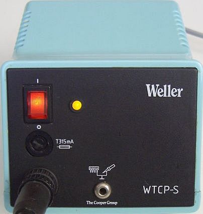
ON/OFF INDICATION
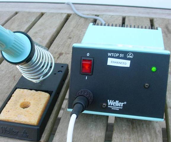
A Weller soldering station is in my opinion one of the best purchases for a DIY radio amateur. At government repair facilities, these tools are switched on at 0800 hours the start of the working day and switched off at 1700 hours at the end of the day and that year in, year out. A solid product, but too much money for what it contains.
The station has been working for me for 25 years without fail. I found one objection that you could not see whether the soldering iron was already at temperature. A simple (fig») and not unknown circuit ensures that the light (LED) goes out when the correct temperature is reached
RELIEF SWITCH ELEMENT
In 1996 PA1AIS devised a circuit to relieve the switching element. Previously every few years there were problems and he finally got enough of it.
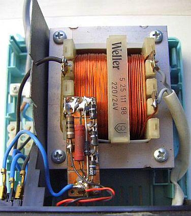
With his modification, a maximum of 11 mA passes through the switching element and the heating element is switched on during the zero crossing of the 24 VAC. It works with a 'power switch zero-cross power-on triac' or 'zero-crossing optotriac' of SHARP type S216S02. The latter has more or less become obsolete, but a replacement can be type CPC1998J of IXYS.
When the switch closes, the 7805 stabilizer is supplied by the rectifier with paralleleled elco. The 7805 is connected as a constant 11 mA current source by the 470 ohm resistor. The current causes the LED to light up so that the triac starts to conduct. Simplicity itself, but to make the circuit work, a three-wire cable is required. That is missing in a WTCP, but is standard with a WTCP-S!
Thanks to its design, PA1AIS has been enjoying his soldering station for more than 22 years and it is expected to last longer.
TO HOT 7805 STABILIZER
Ad Hardenberg wrote to me that it was not easy to get a CPC1998J, but it was possible through the company TME (Transfer Multisort Elektronic B.V.). He had some problems with the uA7805, because that type got quite hot in a test setup, while a second uA7805 even failed. According to him, this was caused by the input voltage of 34 VDC, which is very high for the IC. The voltage at the input may be a maximum of 25 Volts. That is why he used an LM317 as a constant current source of 10 mA. A maximum of 40 Volts may be used at the input.
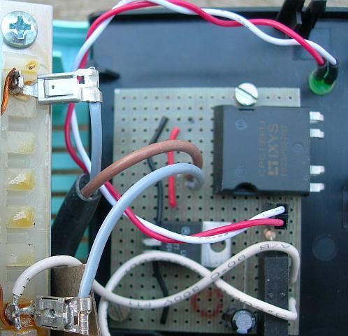
Ad Hardenberg's modificatie op een stukje gaatjesprint.
![]()
![]()